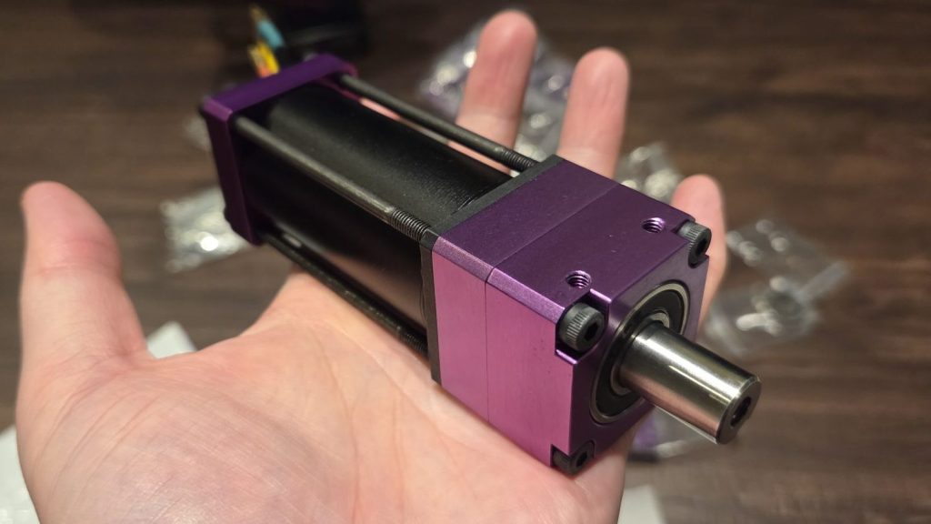
Earlier this May I took MegatRON to NHRL’s first Pro Tour for the 2026 season where it faced against some of NHRL’s best to place second in a NARROW loss to Kazaa Lite. One of the standout issues of the event was the first gearbox related failure for this version of MegatRON. Historically drivetrain issues were due to the treads or the motor fragility but this time the output-stage planetary teeth had failed and the sun, planets, and ring gear would need to be replaced.
Annoyingly, BaneBots no longer sells individual parts for the P6 gearboxes. While investigating alternate gearboxes which would sell individual components, I had the idea to explore other reducer technologies altogether. What if I designed a gearbox that could be machined? I was already comfortable with precision machine design and already had great suppliers.
Enter the cycloidal reducer; a type of gearbox which uses an eccentric drive cam to rotate a lobed disk housed inside a ring of pins by wobbling it one pin at a time. The output shaft is synchronous to the lobed disk thusly achieving a reduction in speed and amplification in torque. It is conceptually similar to a strain-wave gear in that it “steps over” one tooth per input rotation except it does not rely on deformation of a flex spline which makes it more compact, shorter in axial length, more resilient to sudden impact, and easier (for me) to have fabricated. It loses on backlash and reduction ratio per volume but neither of those parameters are important for this application.
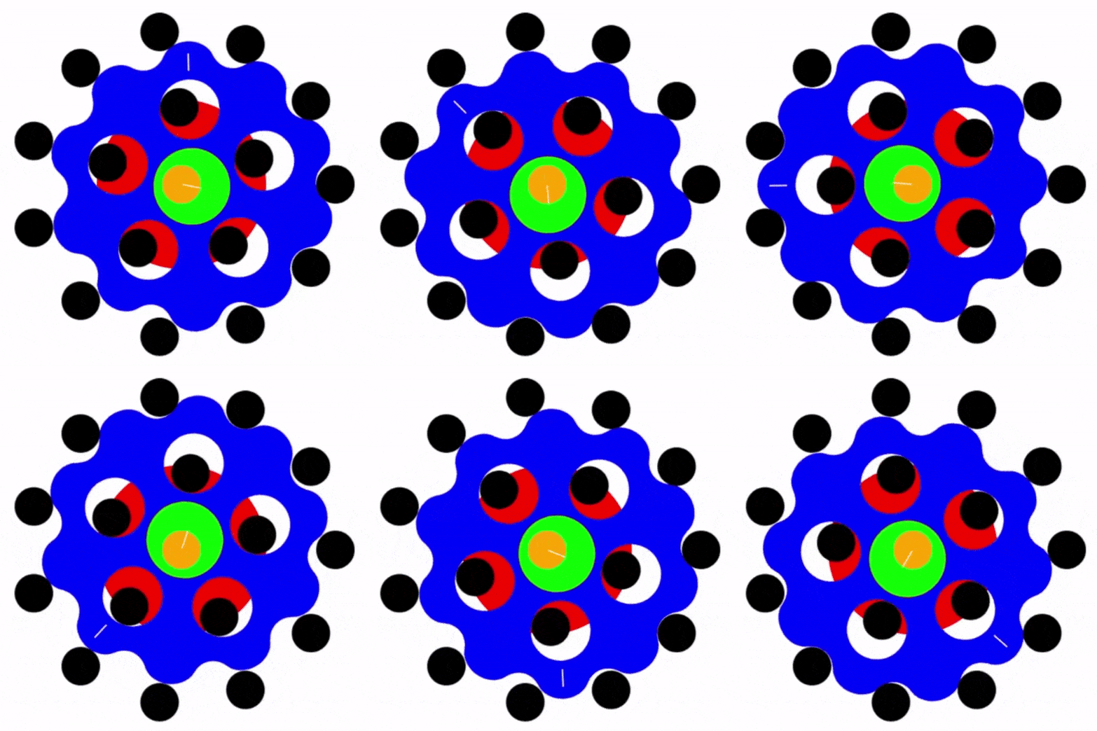
The neat thing about cycloidal drive design is its almost entirely parametric and all those variables roll into a single complex part, the disk.
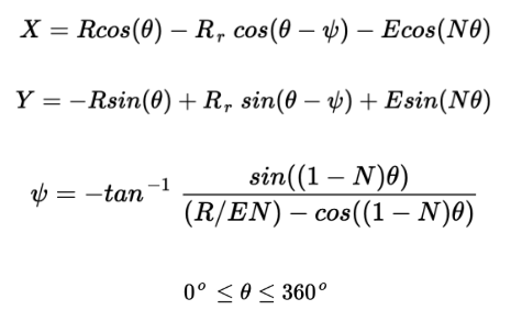
Where R is the location radius of the outer pins, E is the eccentricity of the cam, R_r is the radius of the pins, and N is the number of rollers. To implement this in SolidWorks, I used the parametric inputs for equation driven curves as a starting point but ended up patterning a section of the disk N-1 times.
These equations only control the disk design according to the pin diameter, location radius, and quantity. The output parameters and internal bearing selection are still up to the user.
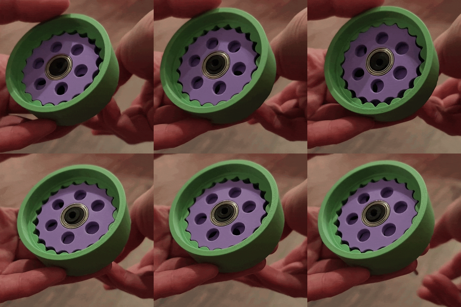
I verified my understanding by quickly building a single-disk prototype. Each piece was made from matte PLA on my Bambu X1C.
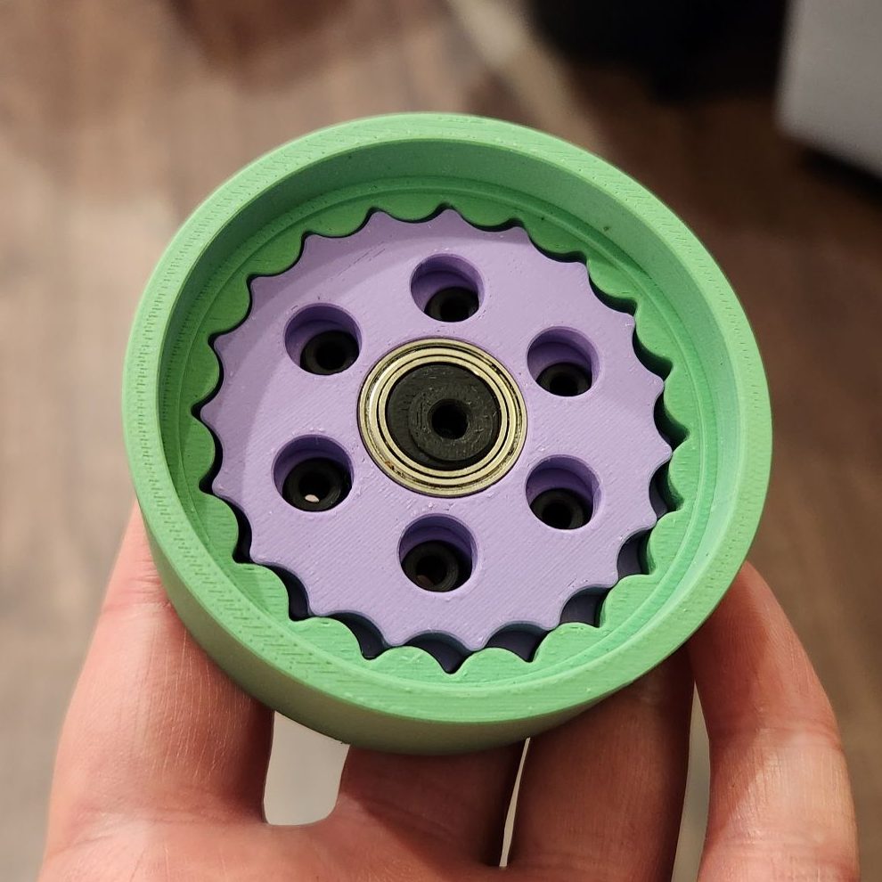
Now to design a prototype for MegatRON. Basic requirement is to maintain the same gearbox cross section but reduce in axial length and increase robustness. I am not expecting this design route to reduce cost immediately but these main benefits could outweigh the costs over time with longer life and selective replacement of individual components. With a 1.5″ square bounding dimension, I began to size and layout the other components based. I used the planetary design as reference for what “should” work for the pin diameters and bearing sizes. I went with a two-disk design for better load sharing and balance.
At this cross-sectional area restriction, I found the range I was comfortable with was approximately between 13:1 and 21:1. Any smaller and the tooth engagement was too minimal, any larger and the tooth itself was too minimal. I was also fighting to maximize eccentric bearing size and maintain enough real estate for the output pins. The output pin bores in the disk are at minimum the pin diameter + the eccentricity so I ended up dropping the pin diameter from 1/8″ but increasing the plurality of pins.
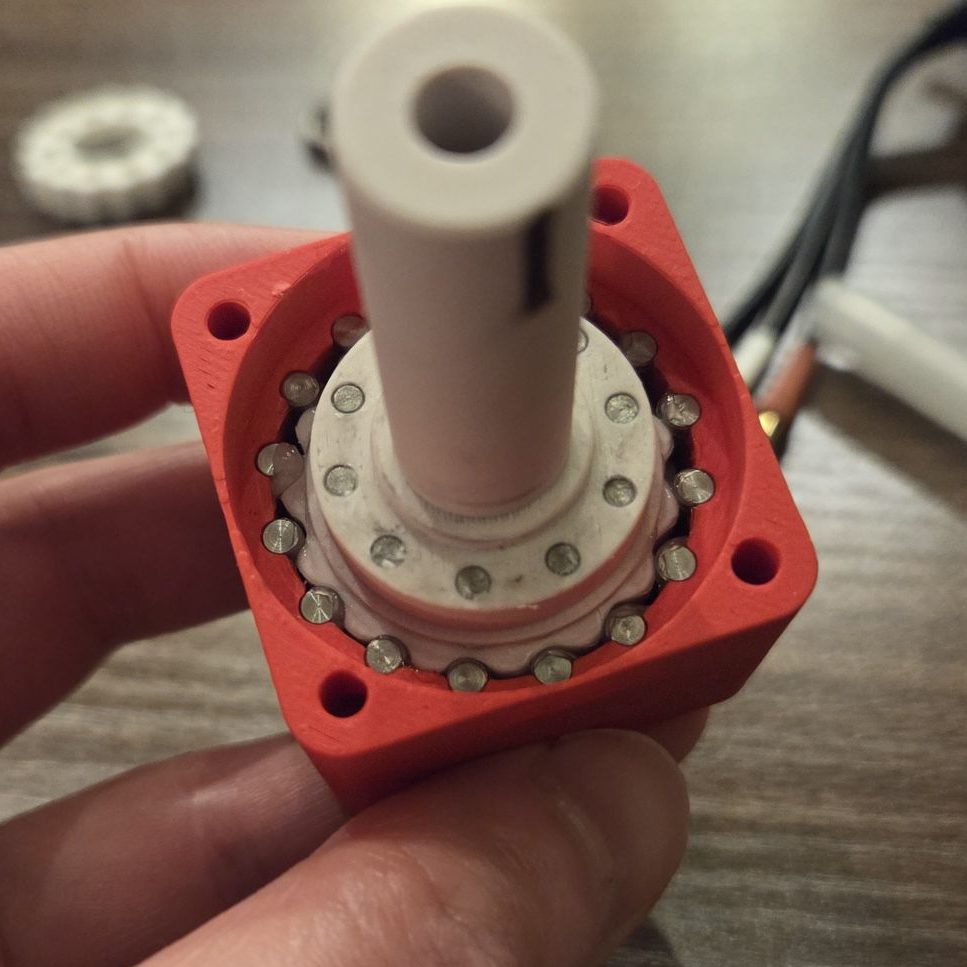
Since I didn’t have a motor selected yet, I designed a generic shaft input similar to modern servomotors. The camshaft featured a 5mm through bore with a slotted extension. A thin clamp collar went over the slotted extension to form a collet that would grip any 5mm motor shaft.
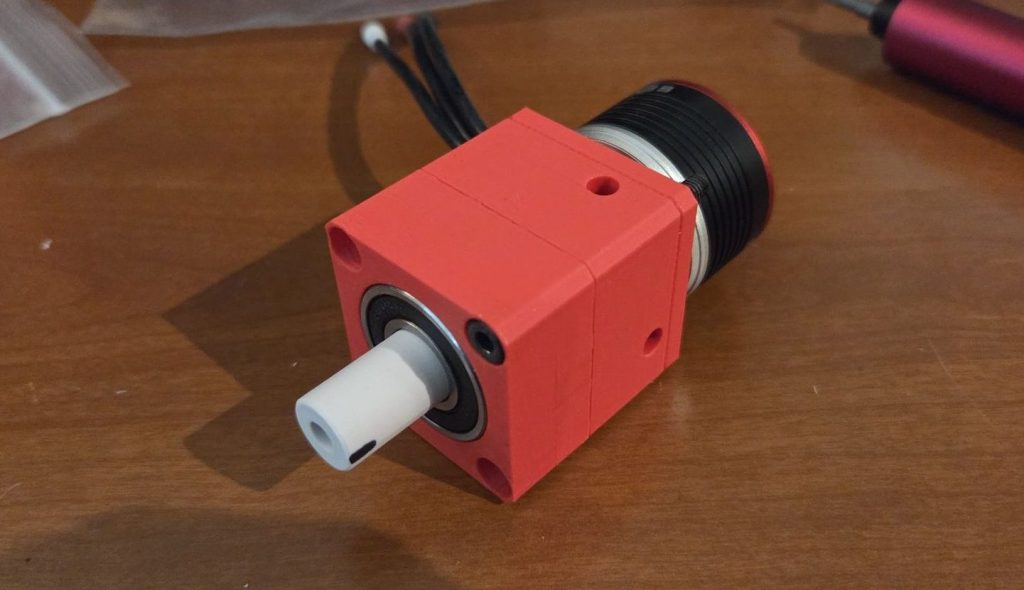
Tested below at 14.8v with a BadAss 2814, 1350 kv motor.
At this stage I was feeling confident I had understood the fundamentals of generating working geometry; and it was time to start flushing out the specifics of my targeted application: MegatRON’s drivetrain.
I created a tradeoff table to down select on the targeted ratio. The current solution (22:1 overall ratio driven by a TP Power 2940) was a happy reference point for performance. Since I was building from scratch, alternate motors were also a design possibility. I decided to increase the motor size to a 36mm inrunner to address a theory I had regarding my motor failures. Essentially, bigger motor -> larger motor shaft (5mm, previously 4mm) -> less deflection. The larger motor also allowed for lower Kv options with a higher power threshold. Ultimately I decided to proceed with a 17:1 ratio and a 3674-szied, 1300 kv motor which should allow me to push motor up to 1000W harder to compensate for the lower reduction.
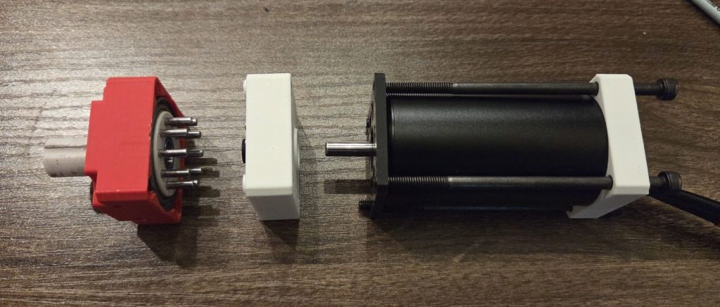
To slim the axial length, I employed two tricks. First I noticed if I decreased the output pin location diameter, I could fit the ring bearing over this portion of the output shaft meaning I could fully embed the output shaft in the frame rail! I also realized I could remove the collet input and change the cam round bore into a slip fit D-bore. This reduced the core reducer portion to a slim 13mm!
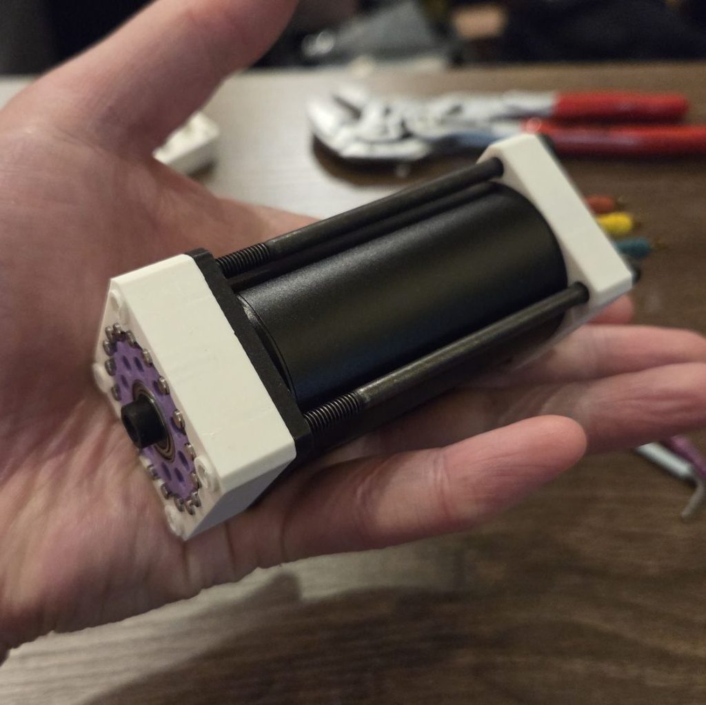
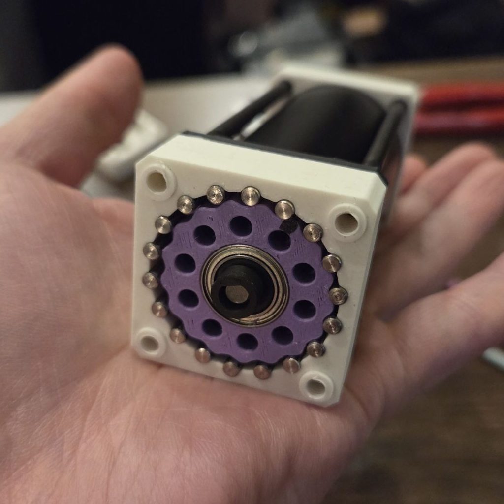
With the design verified, it was time to give this project its official name and get its parts on order. Introducing, the CycloDrive!
Part 2 coming soon!