Immediately following the April NHRL event (with the exception of moving apartments), I went to work on Saiko! AGAIN; I would be bringing Saiko! to NHRL Teams on June 1st, a special mid-year event where competitors would register in teams of three robots, one from each weight class. But more on that later!
While Saiko! did objectively well in April, many things went wrong. I was able to lean on skill and luck to make 2nd place but as I always say, design is the most dependable and consistent path to victory. Let’s review the post-event observations that can be more/less be organized into electrical and mechanical:
Electrical
- Not enough battery
- Weapon esc smoked
- Drive startup inconsistent
Mechanical
- Shaft pins pulled out
- Rear frame screws failed
- Armor mount pulled out from side rail
- Fork mount hardstop snapped
Some of these items were identified prior to the event and would be easy to fix. Such as drive startup performance being solved by re-installing the higher 27:1 gearbox ratio. Others would require testing, re-specifying components, and new designs for parts altogether.
Structural Changes
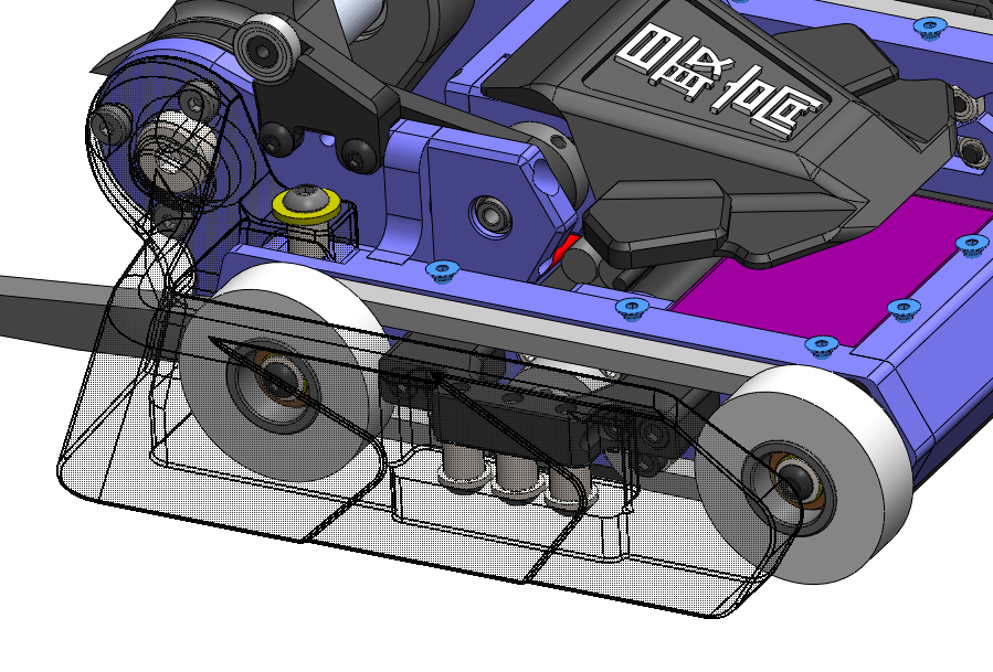
I was overall satisfied with the structure of the machine but wanted to make a few edits to increase robustness. While I generally do a phenomenal job at keeping damage to the front and sides, damage to the rear is possible with loss of control and the result is catastrophic. Similar to the front bulkhead, I added a mechanical keying feature to brace the frame from impacts.


The side rails were pocketed an 1/8″ on the ends while the rear frame member was elongated by a 1/4″ total and intersected with the volume of the frame rails. The interference between the frame rails offers resistance to inward impacts by loading the frame elements in addition to the screws.
The v2 new armor mount was an upgrade to serviceability in that the screws were accessible from the outside and could be replaced more easily. However the screw size was reduced from 1/4″-20 to 10-32 in an attempt to keep the same footprint which created a weak point in tensile or bending loads. Most loads are in compression; a hit on the armor would load the armor mount into the frame and bypass the fasteners. But on the off chance an opponent comes over the top and pulls on the armor mount, I’d be in trouble.
V2.1 doubled the number of 10-32 fasteners for additional strength, now ~25% more shear area than 2x 1/4″-20 screws. Since the frame was made longer, I could also make the armor mounts longer. I also changed the material from steel to 6061-T6 aluminum with the intention that these are the mechanical fuse vs the screws.


With the frame changes finalized, I sent them off to be made by my favorite overseas manufacturing company, LT Century Prototype! Frame pieces once again made from 7075-T6 anodized to Saiko!’s signature aquamarine blue.
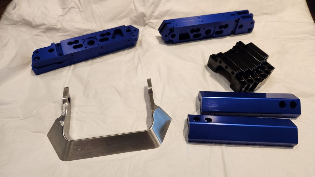
Hey wait, what is that object in the lower left? Since the full competitors list was available to the teams, I investigated the idea of a ridiculous billet wedge to counter the devastating undercutters in the field. This solid 4140 steel part was hardened to HRC50-55 and razor sharp on the leading edge.

I also ventured to guess it would be equally effective at combatting the TPU forks which are becoming increasingly prevalent. We’ll test this theory when it comes time!
Weapon watt meter testing
While the frame parts were on order, I used the old chassis to investigate the weapon system current draw and capacity. These tests would be about comparative measures between the two units and some basic benchmarking for runtime. I left the weapon systems were unmodified from the end of the event to retain as authentic conditions as possible. The singular working mamba X would be passed between each Saiko! along with a watt meter and 6s battery.
Saiko 2
- 30% throttle: 1 A
- 40% throttle: 3 A
- 50% throttle: 9 A
- 100% throttle: ~80 A
- 0 to 100 peak: 150 A
A Pretty reasonable result but somewhat high at max throttle. I know some of this is related to the inefficient geometry of beater-type weapons. I would have loved to do a full characterization like Pete did for Night Crawler but I am borrowing a parking garage and need to be quick. Upon disassembly I noticed some interesting circumferential color bands along the shaft.

All four bearings were shot. At some point in the tournament (probably this one), this unit has been running steel on steel! That might explain higher the current draw and if I had tested for longer, increased current draw over time as things heated up and expanded.
Saiko 1
I didn’t get very far because it was clear something was very wrong. At 50% throttle it was pulling 30 A. If you recall, this was the unit which immediately blew its weapon esc and so the mechanicals were practically new. I am glad I did not try the 0-to-100 throttle test on this motor.
I performed some resistance measurements on the motor. The 9D wind for the TP2940 motor is supposed to be 15 mOhms per phase which is pretty small; for this, I used the four-wire Kelvin measurement technique and measured phase resistances of 24 mOhms. Honestly I was expecting a lower resistance value indicative of a short. Higher resistance might imply a strand within a phase was lost; the overall current and torque capacity would be decreased. Perhaps the ESC tried a little too hard to turn over the weakened motor too fast. In any case, this result spooks me and this motor is being set aside for parts or further investigation.
Electrical Hardware Changes
Based on the watt meter testing and mechanical inspection, it was clear I would need more capacity. In addition to the current draw tests, I also performed some runtime tests. Using an older 4s 2300 mah pack, I ballparked the consumption to 1.1 Ah using a weapon spin profile. I simultaneously decided to drop cell counts to buy more voltage margin against the ESC hardware limits. This Tattu 5s 2200 mah 95C pack should allow for longer runtimes and equivalent burst current despite the lower C rating.
To fit the new battery, I actually needed a few millimeters of width. I redesigned the MS-05 Whyachi switch casing to be slimmer and printed it out of fiberglass-reinforced nylon.


I had also changed out the ESCs in the bot. Since I was now running a 5s system, I returned the the Emax 45 blheli32 ESCs which have been a winning combination in the past and I have six of them. I was less worried about the hardware limits on these because the required motor effort would be low with the 27:1 gearboxes reinstalled. For the weapon, I swapped to the Rhino 80A AM32 crawler ESC. I have been using these on MegatRON for drive and blade with great success. With the current limit to 65 A, I was still able to measure peaks of ~100A under very quick throttle changes but for slower commands the limiting remained true.
Aesthetic Upgrades
For the teams event, we were encouraged to look good and I put some effort into texturing some elements and making the machine look more polished overall. The top plates were extended in width to cover the chains and a top TPU part was added to cover the motor. Since it obscured the previous home of the logo, I moved “Sai-Kou” to the TPU part. The top plate extensions also offered nice locations for our team’s sponsors, SendCutSend and Repeat Robotics!


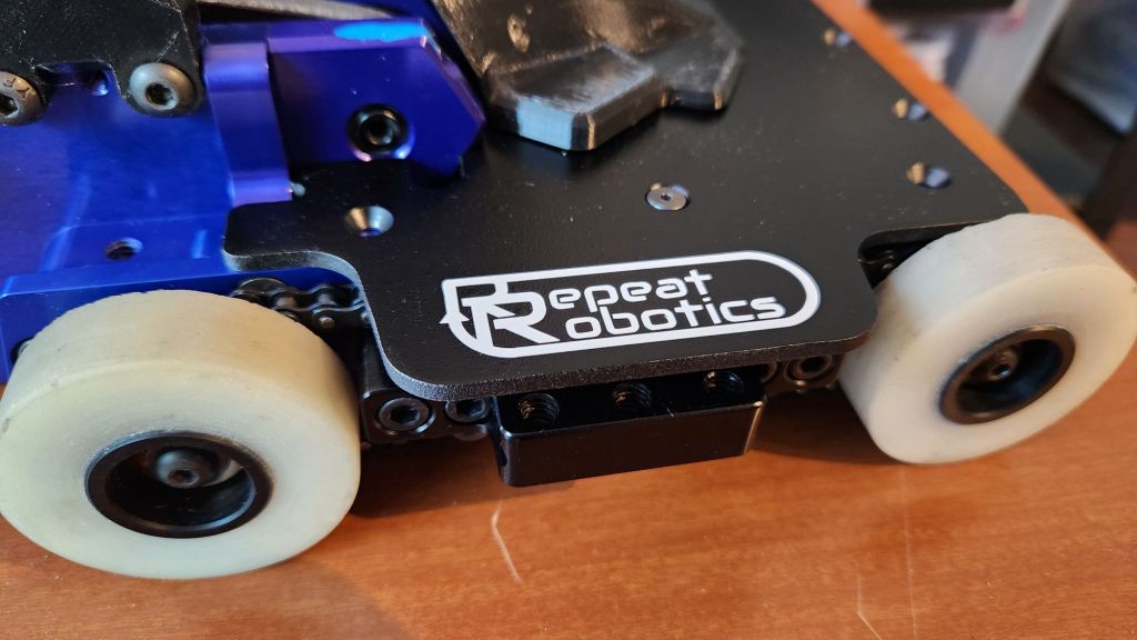
All vinyl work is done myself on my Cricut Maker 2!
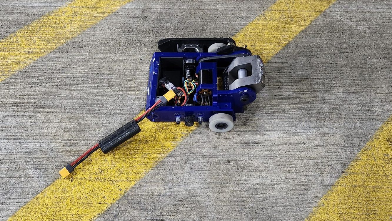
All Done!
With all these changes implemented, Saiko! 1 & 2 were ready to rock for June 1st! Shown below is Saiko! 1 which just needs forks before its fight with Robocat. Saiko! 2 is configured for a special armor for its first round opponent, Caldera 12! More on that later!


